
Description
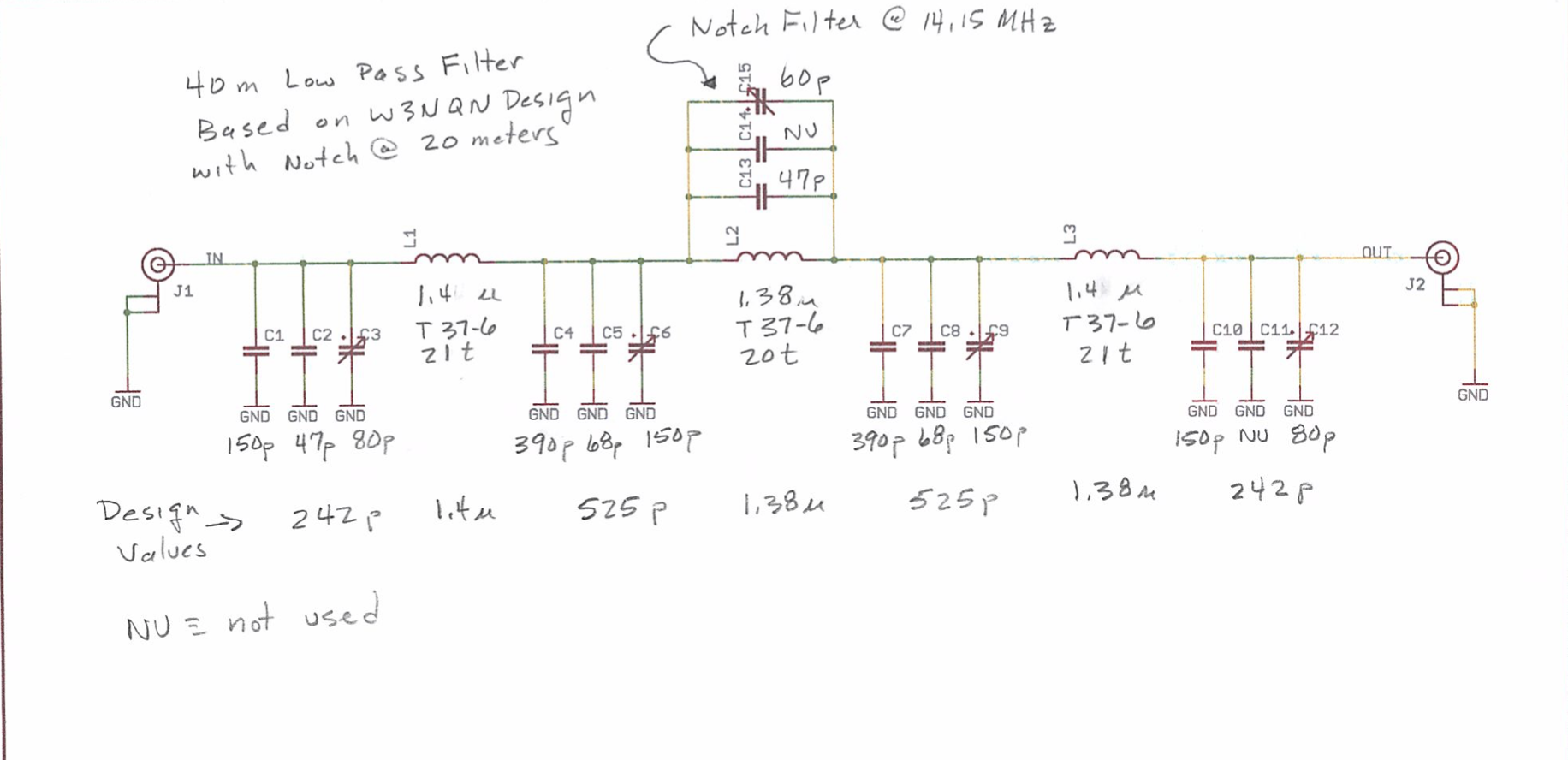
This low pass filter is designed for the HF bands and is based on the design by W3NQN. It has a good low pass response and a extra capacitor is added to make a notch filter at the 2nd harmonic. This makes the filter ideal for transmitter outputs. I built one for 40 meters, and the design should work well for all the HF bands.
See below for the Schematic, PCB layout file, and link to purchase three bare pc boards from OSH Park at cost.
A video is available that describes checking the circuit out with SimSmith, a very useful circuit analysis software program. (coming soon!)
Additional information and component values for all the bands are available here.
Files
Downloads:
Click here for the Schematic PDF file
Click here for the Eagle Schematic file
Click here for the Eagle PCB Layout file
Parts
This project does not require many parts, and most are available from Mouser. Bare PC Boards are available from OSH Park.
| Qty | Part | Value | Package | Vendor | Part Number |
|---|---|---|---|---|---|
| 1 | C1,2,4,5,7,8,10,11,13,14 | Misc. chip ceramic capacitors | 0805 | Vishay Multilayer Ceramic Chip (COG) | e.g. 77-VY0805A180JXACBC |
| 1 | C3,6,9,12,15 | 6mm Trimmer capacitors | 6mm diameter | Amazon, danssmallpartsandkits.net, eBay | |
| 1 | L1,2,3 | Toroids | www.kitsandparts.com | ||
| 2 | J1-2 | SMA Female Jack | PCB Edge Connector | Amazon | Order Link |
| 1 | PC Board | OSH Park | Order Link for 3 boards |
Part values for each HF band are here. I recommend that you test each circuit in SimSmith to get the performance that you are looking for.
Three bare pc boards are available at cost from OSH Park.
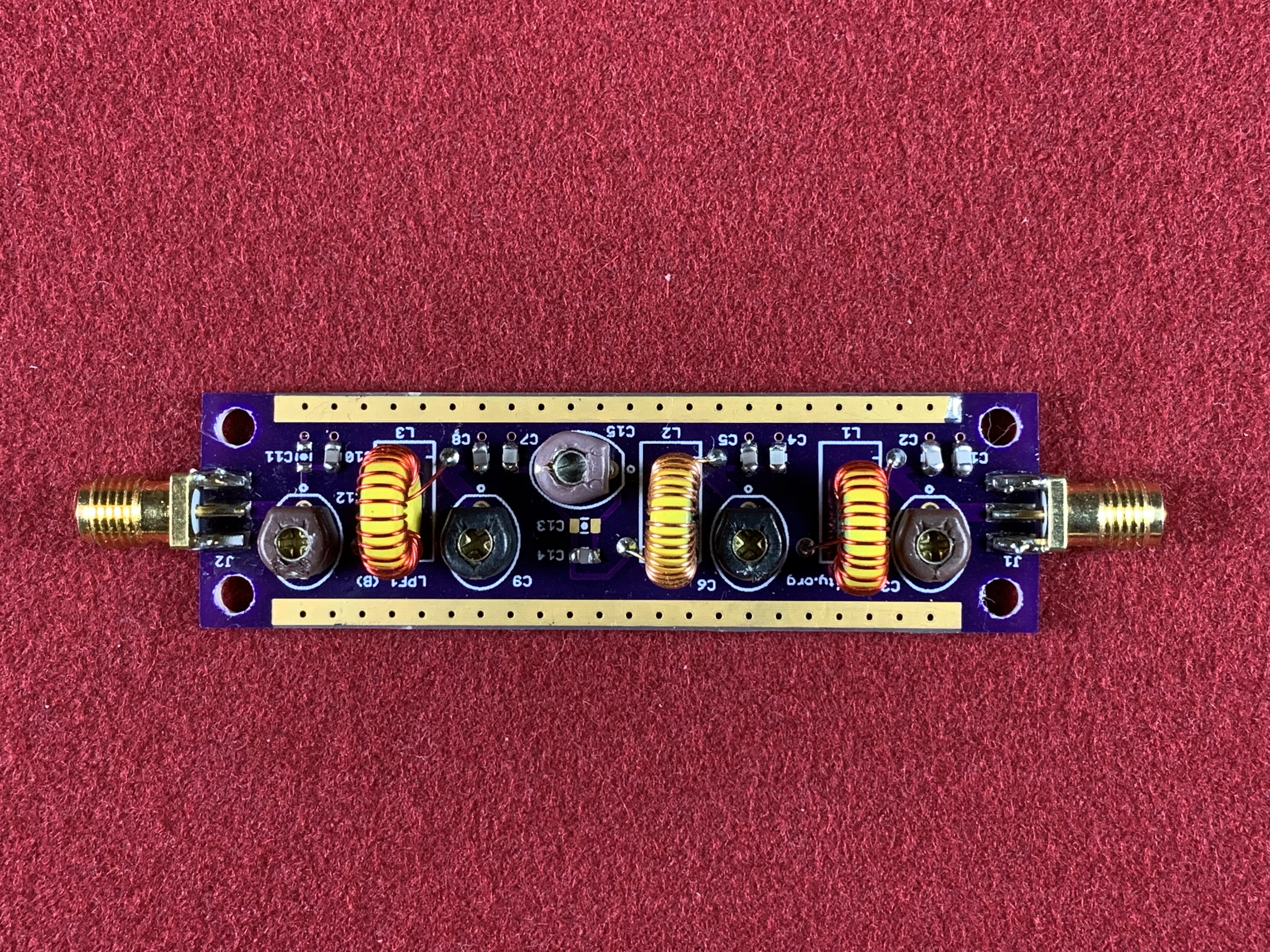
Assembly
Assembly is straight forward. I suggest soldering parts in this order: chip capacitors, variable capacitors, toroids, and finally the SMA connectors
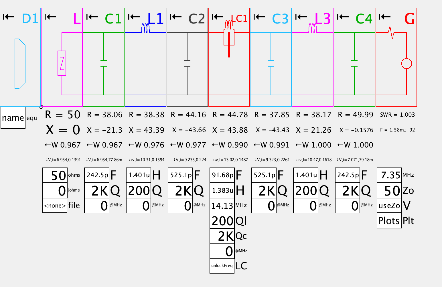
Tuning
SimSmith is a very useful program for analyzing RF circuits. You can input your circuit and then tune each component by rotating your mouse wheel and watch the insertion loss and SWR (or return loss) in real time. This allows you to see what each component does in your circuit. SimSmith tutorials are here.
To test and align your filter a Vector Network Analyzer, such as the under $100 nanoVNA (available on Amazon), is a wonderful tool that lets you see insertion loss and SWR all at once.
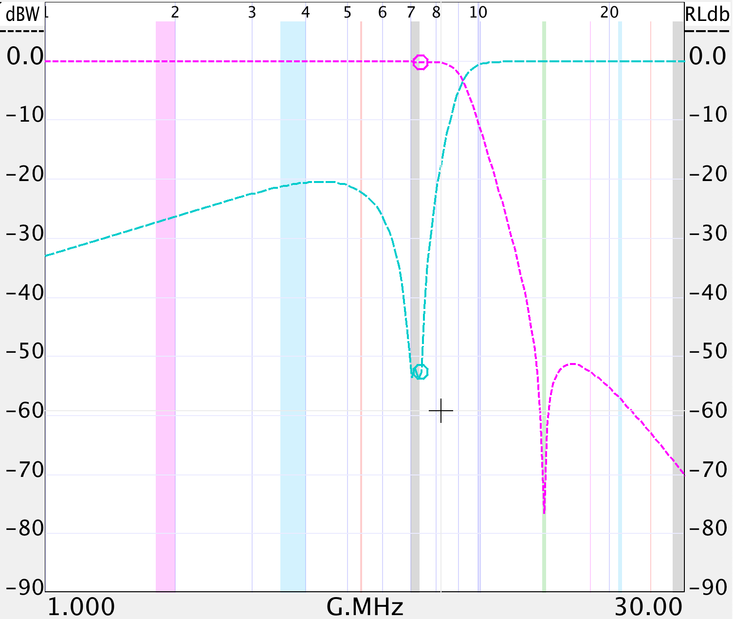
Performance
The final schematic for the 40 meter filter with final component values:
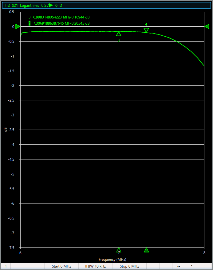
The 40 meter insertion loss is less than .2dB (the arrow markers show the edges of the 40 meter band)
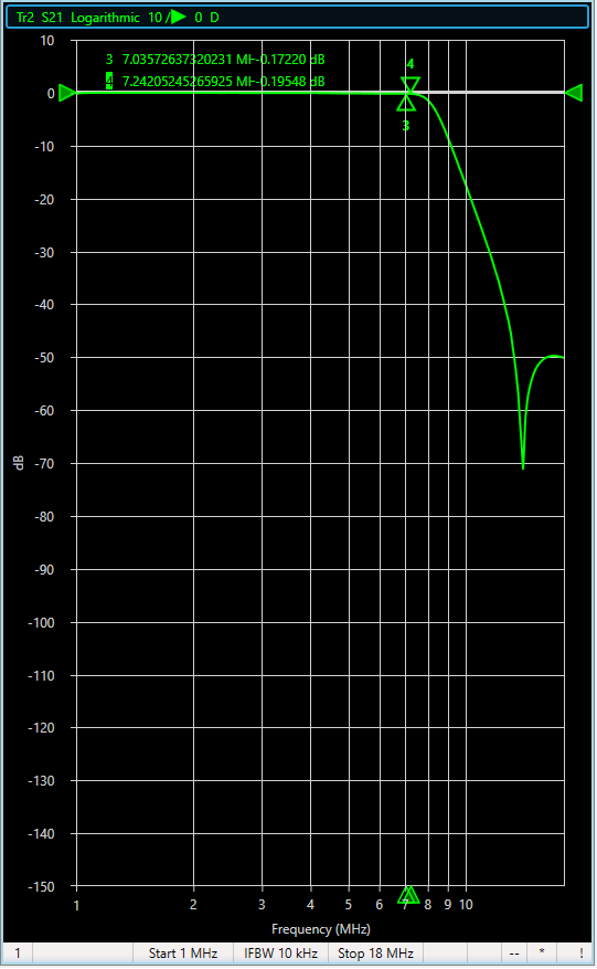
The insertion loss of the 2nd harmonic at 14MHz is greater than 50dB.
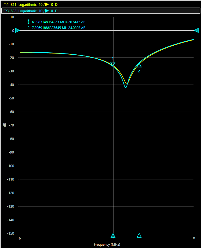
The in band 40 meter return loss is better than 20dB.
License Information
Our License Information is here.
Leave a Reply