
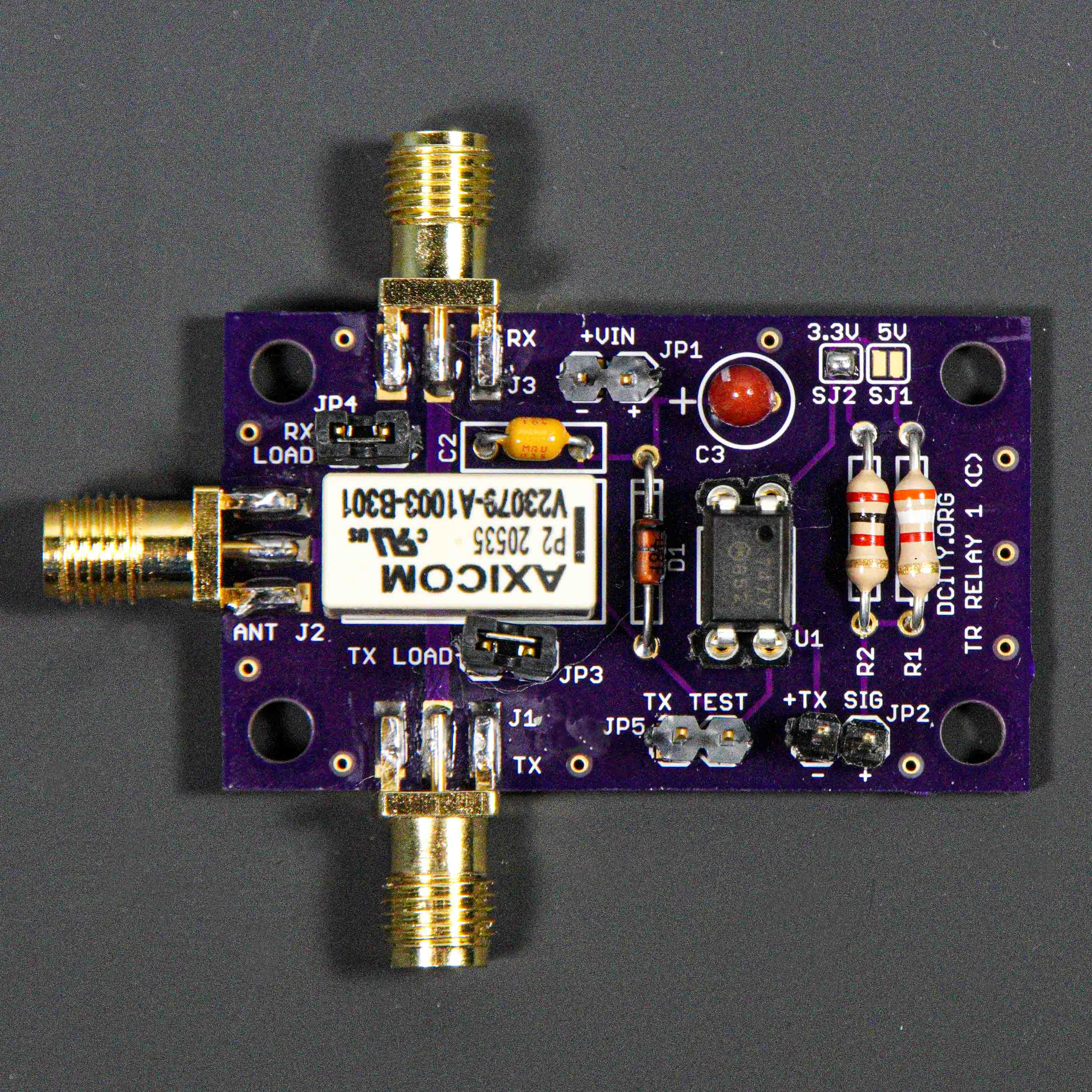
Description
This RF relay board is a simple transmitter/receiver relay board that switches the Antenna to either the Receiver or the Transmitter. Of course it can be used to switch other RF signals inside a radio. I use it several places in my radio projects. The RF performance is good for a low cost board (see performance graphs below). Schematic and Eagle PCB design is provided. You can order bare boards directly from oshpark.com.
There are several ways that the TR relay can be activated to switch the Antenna to the TX connector.
- Apply 12 volts to JP1 (Vin) and install jumper JP5. The relay will be activated whenever 12 volts is applied and the jumper is in place.
- Apply 12 volts to JP1, and connect an open collector output to pin 2 of JP5. Whenever pin 2 is brought to ground, the relay will be activated.
- Apply 12 volts to JP1, disconnect jumper from JP5, and apply a 3.3 or 5 volt signal to JP2. This is an opt-isolated interface so that this rf board can be ground isolated from your microprocessor section (good for reducing ground loops, hum and noise). You can connect these pins to the microprocessor in two ways:
- Connect pin 1 of JP5 to the ground on your microprocessor board, and connect pin 2 of JP5 to a microprocessor output pin. When this output pin goes high, the relay will be activated (TX mode). Approximately 1mA of current is needed to trigger the opt-isolator. Solder across jumpers SJ1 or SJ2 based on what your microprocessor supply voltage is.
- Connect pin 2 of JP5 to the supply voltage on your microprocessor board (either 3.3v or 5v), and connect pin 1 of JP5 to a microprocessor output pin. When this output pin goes low, the relay will be activated (TX mode). Approximately 1mA of current is needed to trigger the opt-isolator. Solder across jumpers SJ1 or SJ2 based on what your microprocessor supply voltage is.
See below for the Schematic, PCB layout file, and link to purchase bare pc boards from OSH Park.
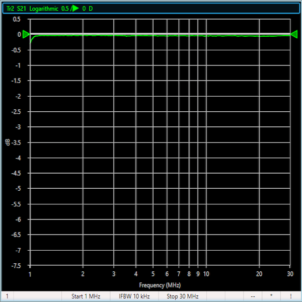
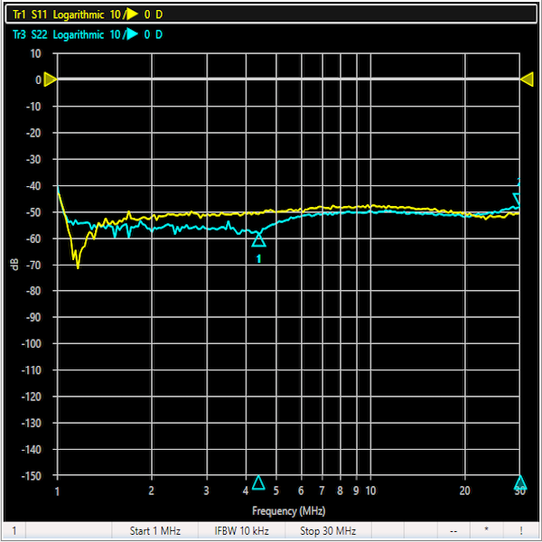
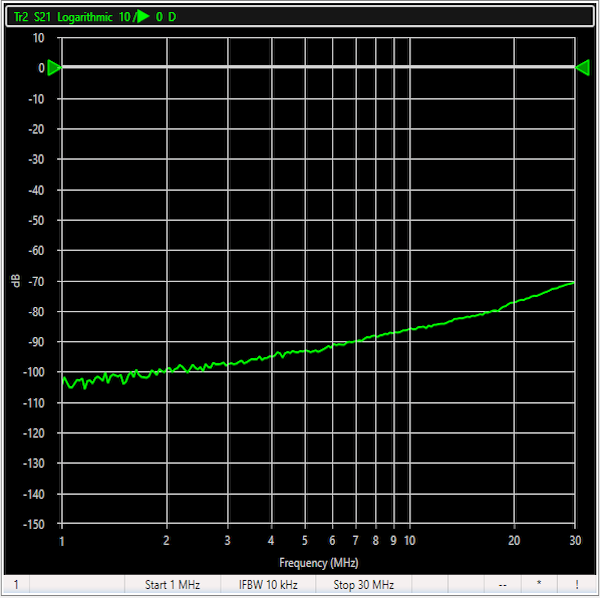
Performance
The insertion loss between the Antenna and the RX (or TX) is less than .3dB from 1-30MHz.
The return loss (related to SWR) looking into the Antenna port or the RX port (when in RX Mode) is greater than 40 dB from 1-30 MHz (better than 1.1:1 SWR). The return loss (related to SWR) looking into the Antenna port or the TX port (when in TX Mode) is greater than 40 dB from 1-30 MHz (better than 1.1:1 SWR). Looking into the unused port is a direct short (if JP3 and JP5) are in place. This minimizes cross talk between channels when they are not in use.
The isolation between the TX and RX ports is greater than 65 dB from 1-30 MHz.
Files
Click here for the Schematic PDF file
Click here for the Eagle Schematic file
Click here for the Eagle PCB Layout file
Parts
This project does not require many parts, and most are available from Mouser. Bare PC Boards are available from OSH Park.
| Qty | Part | Value | Package | Vendor | Part Number |
|---|---|---|---|---|---|
| 1 | C1 | .1uF ceramic | axial lead (.2” spacing) | ||
| 1 | C2 | 10uF tantalum | radial lead (.1” spacing) | ||
| 1 | JP1-5 | 2 pins | .1 Header Pins | Mouser.com | 855-M20-9991645 |
| 1 | R1 | 3.9K 1/4w | radial lead (.4” spacing) | ||
| 1 | R2 | 2.2k 1/4w | radial lead (.4” spacing) | ||
| 1 | D1 | 1N4148 diode | radial lead (.4” spacing) | ||
| 1 | U1 | FOD852 | DIP4 | Mouser.com | 512-FOD852 |
| 1 | K1 | DPDT Relay | DIP | Mouser.com | 655-V23079A1003B301 |
| 3 | J1-3 | SMA Female Jack | PCB Edge Connector | Amazon | Order Link |
| 1 | PC Board | OSH Park | Order Link |
Bare pc boards are available from OSH Park.
Assembly
Assembly is straight forward. I suggest soldering in the SMA connectors first, as they are the only parts that need to be soldered on top and bottom. Then I start installing the lowest height parts first and work my way up. You can use an IC socket on the opt-isolator (U1) if you want.
Jumpers and Connectors
JP1: Vin 10-14 volts
JP2: Opto-isolated signal for activating the relay
JP3: TX port is connected to JP3 when in RX mode. Connect a jumper across these pins for maximum isolation.
JP4: RX port is connected to JP4 when in TX mode. Connect a jumper across these pins for maximum isolation.
JP5: Short these pins to manually activate the relay. Also see the Description above for another way to activate the relay.
J1: Transmitter RF Connector (is connected to the Antenna connector when relay is activated)
J2: Antenna RF Connector (is connected to the TX connector when relay is activated, else connected to the RX connector)
J3: Receiver RF Connector (is connected to the Antenna connector when relay is not activated)
License Information
Our License Information is here.
Check out the IC SKY13405-490LF: 0.1 to 3.0 GHz Ultra High Linearity SPDT
Switch…perfect for switching…and solid state so it will not wear out
Brian,
That’s a nice part! And only $1.50 in small quantity. It should be good for switching up to 5 watts or a little more. Thanks for letting me know. I’m going to order a few.
Gary
Oh yeah…absolutely, would probably work EXCELLENTLY in say a handi-talkie repeater build…especially with it’s excellent db isolation on the off relay setting